+91-9687689987
for more information
| Item | Specifications | |
| Input | Inuput Voltage | 3 phase 380V-480V:380V~480V |
| Allowed Voltage fluctuation range | -15%~10% | |
| Input frequency | 50Hz / 60Hz,fluctuation less than 5% | |
| Output | Output Voltage | 3phase:0~input voltage |
| Overload capacity | General purpose application:60S for 150% of the rated current Light load application:60S for 120% of the rated current |
|
| Control | Control mode | V/f control Sensorless flux vector control without PG card(SVC) Sensor speed flux vector control with PG card (VC) |
| Operating mode | Speed control、Torque control(SVC and VC) | |
| Speed range | 1:100 (V/f) 1:200( SVC) 1:1000 (VC) |
|
| Speed control accuracy | ±0.5% (V/f) ±0.2% (SVC) ±0.02% (VC) |
|
| Speed response | 5Hz(V/f) 20Hz(SVC) 50Hz(VC) |
|
| frequency range | 0.00~600.00Hz(V/f) 0.00~200.00Hz(SVC) 0.00~400.00Hz(VC) |
|
| Input frequency resolution | 0.00~600.00Hz(V/f) 0.00~200.00Hz(SVC) 0.00~400.00Hz(VC) |
|
| Input frequency resolution | Digital setting: 0.01 Hz Analog setting: maximum frequency x 0.1% |
|
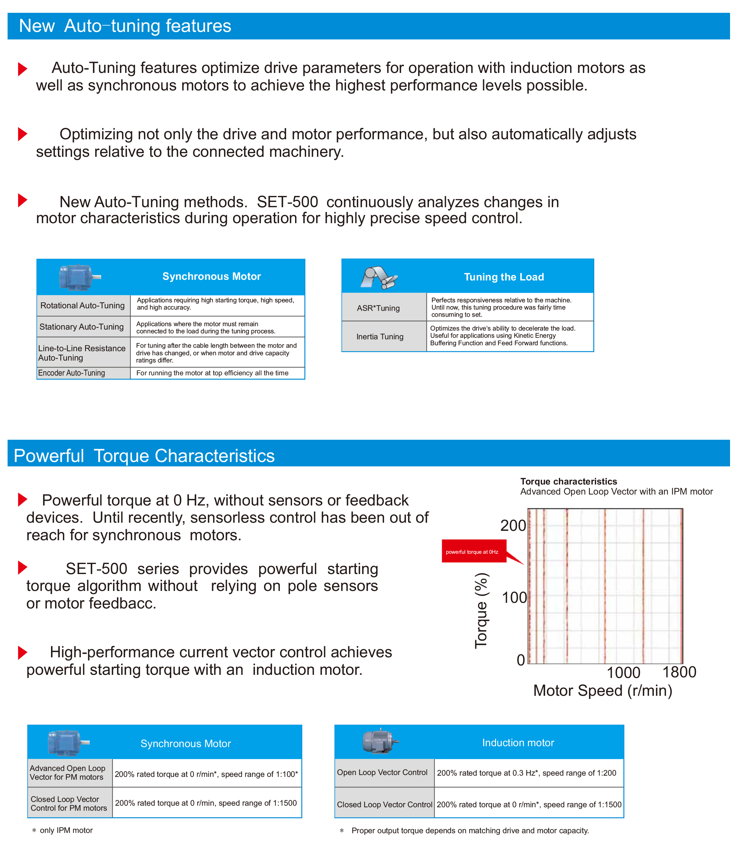
| Startup torque | 150%/0.5Hz(V/f) 180%/0.25Hz(SVC) 200%/0Hz(VC) |
|
| Torque control accuracy | SVC:within 5Hz10%,above 5Hz5% VC:3.0% |
|
| V/f curve | V / f curve type: straight line, multipoint, power function, V / f separation; Torque boost support: Automatic torque boost (factory setting), manual torque boost | |
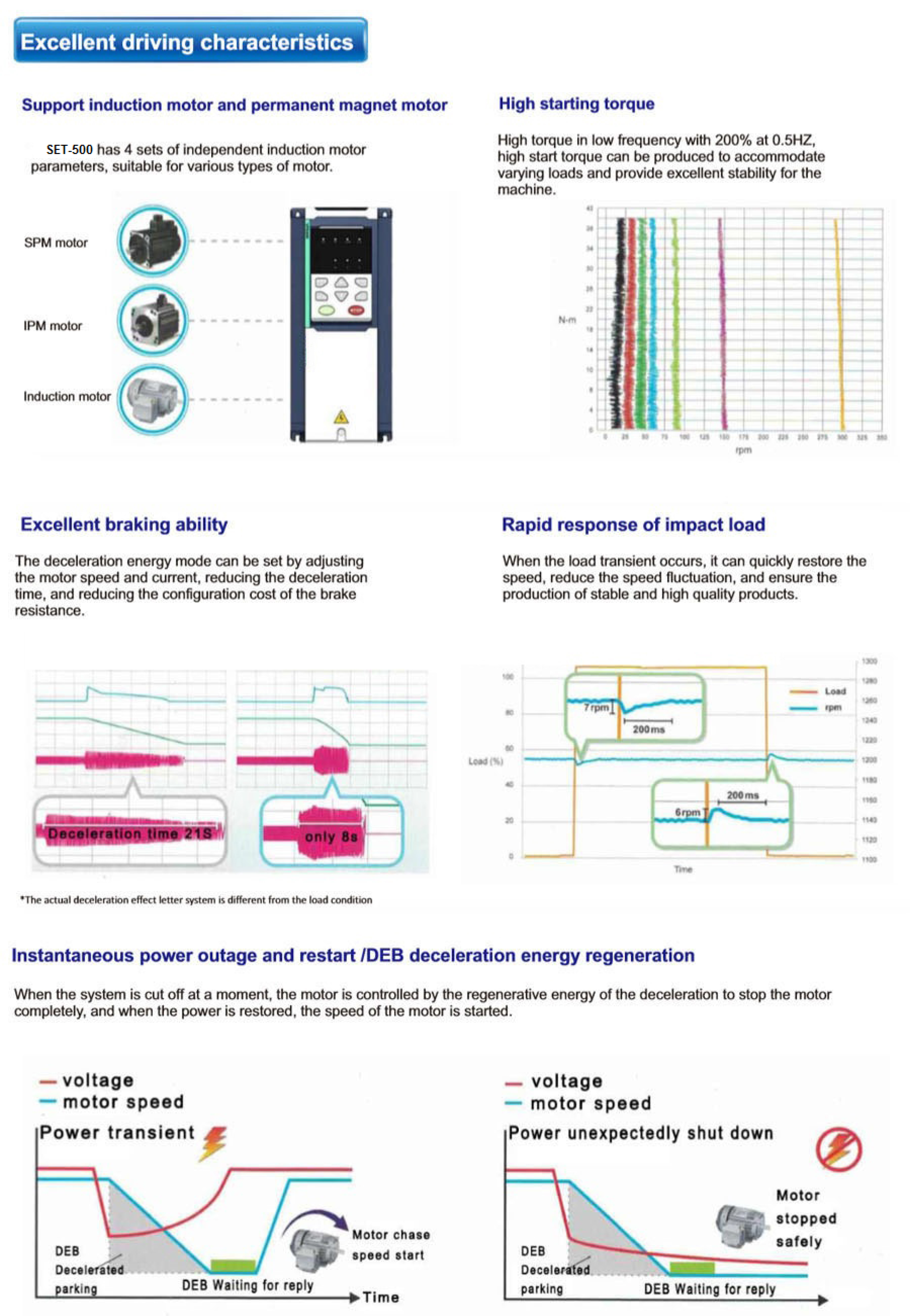
| Frequency giving ramp | Support linear and S curve acceleration and deceleration; 4 groups of acceleration and deceleration time, setting range 0.00s ~ 60000s |
|
| DC bus voltage control | Overvoltage stall control: limit the power generation of the motor by adjusting the output frequency to avoid skipping the voltage fault; Undervoltage stall control: control the power consumption of the motor by adjusting the output frequency to avoid yaw failure VdcMax Control: Limit the amount of power generated by the motor by adjusting the output frequency to avoid over-voltage trip; VdcMin control: Control the power consumption of the motor by adjusting the output frequency, to avoid jump undervoltage fault |
|
| Carrier frequency | 1kHz~12kHz(Varies depending on the type) | |
| Startup method | Direct start (can be superimposed DC brake); speed tracking start | |
| Stop method | Deceleration stop (can be superimposed DC braking); free to stop | |
| Deceleration stop (can be superimposed DC braking); free to stop | Jog control, droop control, up to 16-speed operation, dangerous speed avoidance, swing frequency operation, acceleration and deceleration time switching, VF separation, over excitation braking, process PID control, sleep and wake-up function, built-in simple PLC logic, virtual Input and output terminals, built-in delay unit, built-in comparison unit and logic unit, parameter backup and recovery, perfect fault record,fault reset, two groups of motor parameters free switching, software swap output wiring, terminals UP / DOWN | |
| Function | Keypad | LED Digital keyboard and LCD keypad(option) |
| communication | Standard: MODBUS communication Option:Profibus-DP and CAN OPEN |
|
| PG card | Incremental Encoder Interface Card (Differential Output and Open Collector), Rotary transformer Card | |
| Input terminal | Standard: 5 digital input terminals, one of which supports high-speed pulse input up to 50kHz; 2 analog input terminals, support 0 ~ 10V voltage input or 0 ~ 20mA current input; Option card: 4 digital input terminals 2 analog input terminals.support-10V-+10V voltage input |
|
| Output terminal | standard: 1 digital output terminal; 1 high-speed pulse output terminal (open collector type), support 0 ~ 50kHz square wave signal output; 1 relay output terminal(second relay is an option ) 2 analog output terminals, support 0 ~ 20mA current output or 0 ~ 10V voltage output; Option card: 4 digital output terminals |
|
| Protection | Refer to Chapter 6 "Troubleshooting and Countermeasures" for the protection function | |
| Environment | Installation location | Indoor, no direct sunlight, dust, corrosive gas, combustible gas, oilsmoke, vapor, drip or salt. |
| Altitude | 0-3000m.inverter will be derated if altitude higher than1000m and rated output current will reduce by 1% if altitude increase by 100m | |
| Ambient temperature | -10°C~ +40°C,maximum 50°C (derated if the ambient temperature is between 40°C and 50°C)Rated output current decrease by 1.5% if temperature increase by 1°C | |
| Humidity | Less than 95%RH, without condensing | |
| Vibration | Less than 5.9 m/s2 (0.6 g) | |
| Storage temperature | -20°C ~ +60°C | |
| Others | Installation | Wall-mounted, floor-controlled cabinet, transmural |
| Protection level | IP20 | |
| cooling method | Forced air cooling | |
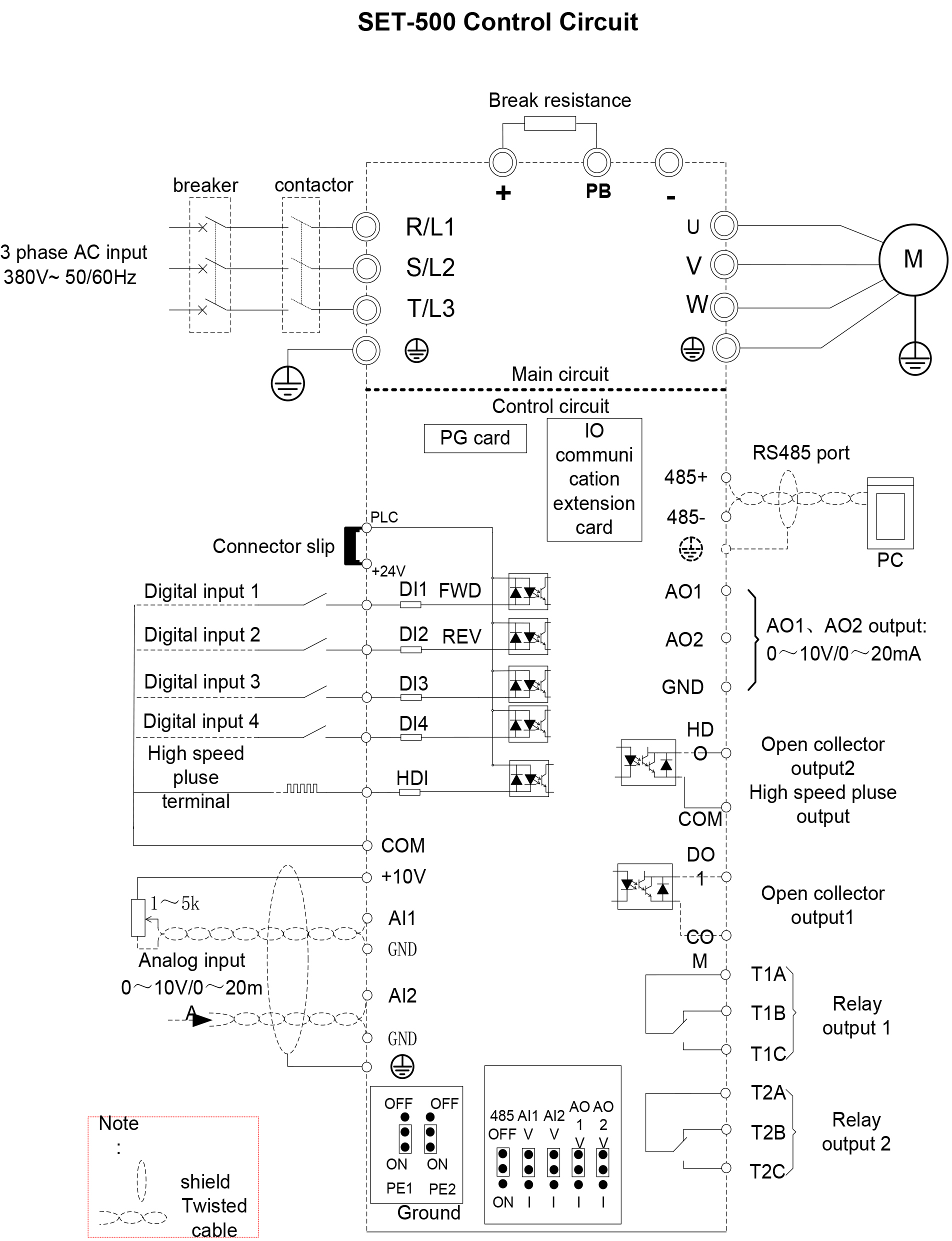
| Type | Terminal Symbol | Terminal Name | Terminal function description |
| Analog input voltage | +10V | Input voltage | 10.10V±1% |
| Maximum output current:10mA,it provides power supply to external potentiometer with resistance range of: 1KΩ~51KΩ | |||
| GND | Ananog ground | Internal isolation from COM | |
| AI1 | Analog input1 | Input voltage:0~10V:Impedance 22KΩ,Maximum input voltage | |
| Input current:0~20mA:Impedance 500Ω,Maximum input current | |||
| Through the jumper switch AI1 0 ~ 10V and 0 ~ 20mA analog input switch, the factory default voltage input. | |||
| AI2 | Analog input 2 | Input voltage:0~10V:Impedance 22KΩ,Maximum input voltage | |
| Input current:0~20mA:Impedance 500Ω,Maximum input current | |||
| Through the jumper switch AI1 0 ~ 10V and 0 ~ 20mA analog input switch, the factory default voltage input. | |||
| Analog input | AO1 | Analog output 1 | Output voltage:0~10V:Impedance ≥10KΩ |
| Output current:0~20mA:Impedance 200Ω~500Ω | |||
| Through the jumper switch AO1 0 ~ 10V and 0 ~ 20mA analog output switching, the factory default voltage output. | |||
| AO2 | Analog output 2 | Output voltage:0~10V:Impedance ≥10KΩ | |
| Output current:0~20mA:Impedance 200Ω~500Ω | |||
| Through the jumper switch AO1 0 ~ 10V and 0 ~ 20mA analog output switching, the factory default voltage output. | |||
| GND | Ananog ground | Internal isolation from COM | |
| Switch input | +24V | +24V current | 24V±10%,Internal isolation from GND |
| Maximum output current:200mA | |||
| To provide 24V power supply, generally used as a digital input and output terminal power supply and external sensor power | |||
| PLC | Digital input terminal common | The factory default setting is connected PLC with +24V Terminal for on-off input high and low level switch | |
| When using the external signal to drive DI1~DI5, it will disconnect the connector slip of PLC with the +24V | |||
| COM | +24V ground | Internal isolation from GND | |
| DI1~DI4 | Digital input terminal 1~4 | Optocoupler isolation, compatible with bipolar input | |
| Frequency range:0~200Hz | |||
| Voltage range:10V~30V | |||
| HDI | Digital input | Digital input terminal:same as DI1~DI4 | |
| terminal /High-speed pulse input | Pulse input frequency input:0~50KHz | ||
| Voltage range:10V~30V | |||
| Switch output | DO1 | Open collector output | Optocoupler isolation |
| Voltage range:0V~24V | |||
| Current range:0mA ~50mA | |||
| HDO | Open collector output /High-speed pulse output | Open collector output:same as DO1 | |
| High-speed pulse output:0~50KHz | |||
| Relay output 1 | TA/TB/TC | Relay output | T1A-T1B:nomal open |
| T1A-T1C:nomal close | |||
| Contact rating:AC 250V,3A;DC 30V,1A | |||
| Relay output2 (optional) | T2A/T2BT2C | Relay output | T2A-T2B:nomal open |
| T2A-T2C:nomal close | |||
| Contact rating:AC 250V,3A;DC 30V,1A | |||
| 485 port | 485+ | 485 Positive differential signal | Baud rate: 1200/2400/4800/9600/19200/38400/57600/115200bps |
| 485- | 485 Negative differential signal |
| Name | Function | Defaults |
| 485 | 485 Termination resistor selection: ON has 100 ohm terminating resistor, OFF is no terminating resistor | OFF |
| AI1 | AI1 analog type selection: V is the voltage input (0 ~ 10V), I is the current input (0 ~ 20mA) | V |
| AI2 | AI2 analog type selection: V is the voltage input (0 ~ 10V), I is the current input (0 ~ 20mA) | V |
| AO1 | AO1 analog type selection: V is the voltage output (0 ~ 10V), I is the current output (0 ~ 20mA) | V |
| AO2 | AO2 analog type selection: V is the voltage output (0 ~ 10V), I is the current output (0 ~ 20mA) | V |
| PE1 | GND ground selection: ON is grounded through the safety capacitor, OFF is not connected | OFF |
| PE2 | COM ground selection: ON is grounded through the safety capacitor, OFF is not connected | OFF |

